Schematic & Bill of Materials
NOTE:
The schematic shows an I2C EEPROM.
This is not presently supported but was added to the production board as it makes no difference to the board production, and may be handy in the future.
As such, this can be omitted from the build.
Non volatile storage is achieved using the "persistent" class available in the ESP32 software suite (uses FLASH memory).
The Bill of Materials and schematic show some errors. The Driver IC should be a 74HCT1G126, not the LVC variant as shown, it must be HCT technology. The voltage regulator should be a LF33, not LM1117
The silk screen overlay has the labels for R4 & R5 transposed. The 470R should be nearest the switch.
Gerber & NC drill design files
The first green PCBs were produced by Seed Studio Fusion, 10 10x10cm boards for $4.90 USD, 2 fit into this area so 20 boards all up for 5USD, a steal.
I can wholeheartedly recommend their services, very good quality, and most importantly, very reasonable shipping rates.
Production PCB considerations
DS3231
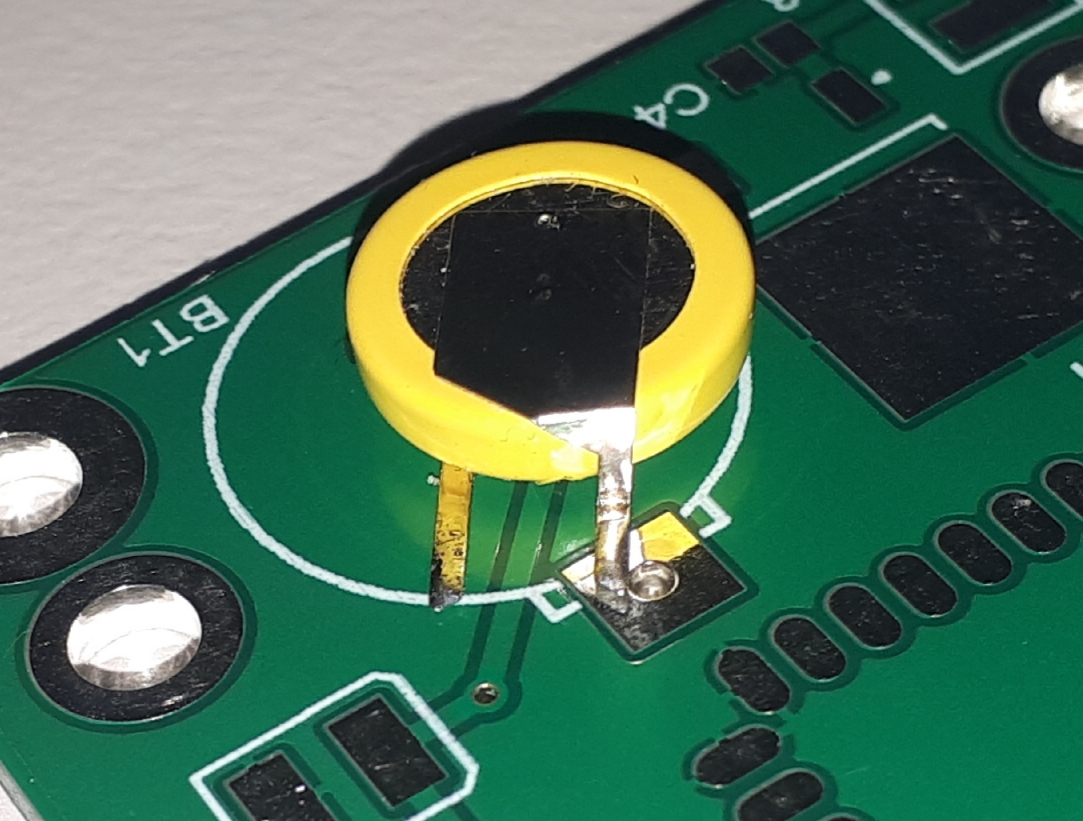
The most cost effective way to source a DS3231 RTC is to obtain a DS3231 Real Time Clock Module For Raspberry Pi from eBay, then use a hot air gun to remove the chip from the module.
As a bonus it comes with a free battery!
The V1 PCB is not designed to take this battery directly, but it could be used as shown in the following image, if some of the solder mask is scraped away to expose the earthy copper:
Special parts for "green board" build
Discrete single pin sockets: eg: RS 718-5284. (low profile)

These sockets are used as the maintain a very low profile compared to the usual 0.1" strip header socket.
They are used in two locations, OLED display & debug port.
-
The OLED can be removed for ready access to the battery terminals should it need to be replaced (optional).
As the PCB holes are very large to accommodate these sockets, should you choose to do so, the OLED could be directly soldered and later easily de-soldered as an alternative. -
These sockets are also used to allow a FTDI232 USB adapter to be plugged in for flashing and debug purposes. (ESSENTIAL!).
M3 Nylon screws and nuts to secure OLED module.
0.1" JST connector sets (3 pin) for attaching to the heater loom, and remote DS18B20 temperature sensor.
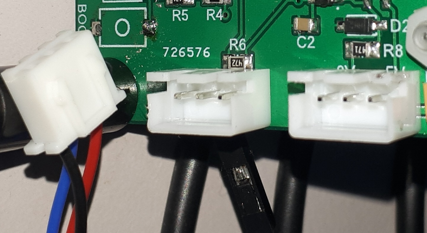
These connections can alternatively be directly soldered to wires if desired.
FTDI232 USB adapter (or similar).
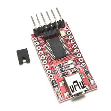
This is essential for the initial upload of firmware into the ESP32.
Once firmware is installed, Over The Air (OTA) programming can be used for future firmware uploads.
Telnet can also be used for debug stream info.