Introduction
The production PCB does not have the bootloader assistance hardware as fitted to the dev boards.
This hardware is usually inferior anyway, typically requiring the hand of man at the right moment to bootload.
The production PCB provides pushbuttons for the EN and BOOT pins, and is actually simpler to deal with once the process is understood.
Required Hardware
No USB support is available on the production PCB.
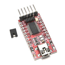
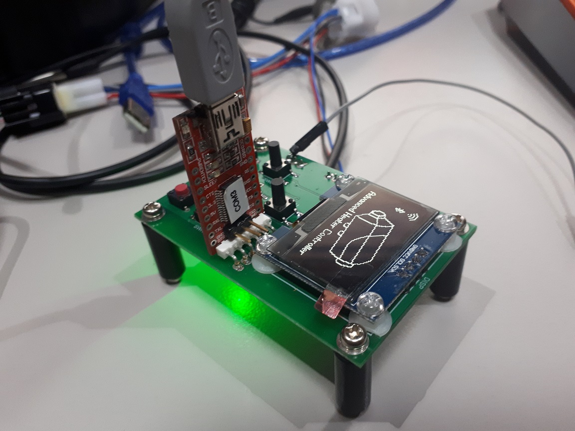
To provide a USB to serial connection, a FTDI232 USB adapter (or similar) is required.
Only the GND, power, Tx & Rx pins are connected on the production PCB.
Note that the ESP32 is a 3.3V processor, so ensure the board is set to 3.3V mode.
In the example shown below, the jumper can actually be left out, and avoids conflicting supplies.
Bootload Process
Prepare the ESP for bootload.
The ESP32 processor needs to be prepared for bootloading by following the following sequence:
- Press and HOLD the EN button.
- Press and HOLD the BOOT button.
- Release the EN button.
- Release the BOOT button.
The above sequence can be performed at any time prior to the upload. It does not need to happen at the moment the upload is being attempted. The ESP32 will simply wait in the bootloader until triggered by ESPtool.
If a serial debug session is active, the following message should then appear:
rst:0x1 (POWERON_RESET),boot:0x3 (DOWNLOAD_BOOT(UART0/UART1/SDIO_REI_REO_V2))
waiting for download
IMPORTANT
Bootloading will fail if the serial debug session remains active.
ESPtool will be unable to use the occupied serial port.
Ensure the serial debug session is closed before the upload takes place.
Upload
After completion of code compilation, the Arduino environment automatically launches ESPtool.exe to upload the generated binary file to the ESP32.
An example (automatic) sequence follows:
Uploading...
esptool.py v2.5.0
Serial port COM11
Connecting......
Chip is ESP32D0WDQ6 (revision 1)
Features: WiFi, BT, Dual Core
MAC: 30:ae:a4:8c:a6:3c
Uploading stub...
Running stub...
Stub running...
Changing baud rate to 921600
Changed.
Configuring flash size...
Auto-detected Flash size: 4MB
Compressed 8192 bytes to 47...

Writing at 0x0000e000... (100 %)
Wrote 8192 bytes (47 compressed) at 0x0000e000 in 0.1 seconds (effective 1092.3 kbit/s)...
Hash of data verified.
Compressed 16720 bytes to 10825...

Writing at 0x00001000... (100 %)
Wrote 16720 bytes (10825 compressed) at 0x00001000 in 0.2 seconds (effective 727.0 kbit/s)...
Hash of data verified.
Compressed 989520 bytes to 546155...

Writing at 0x00010000... (2 %)
Writing at 0x00014000... (5 %)
Writing at 0x00018000... (8 %)
Writing at 0x0001c000... (11 %)
Writing at 0x00020000... (14 %)
Writing at 0x00024000... (17 %)
.
.
.
Writing at 0x0008c000... (94 %)
Writing at 0x00090000... (97 %)
Writing at 0x00094000... (100 %)Wrote 989520 bytes (546155 compressed) at 0x00010000 in 9.9 seconds (effective 803.1 kbit/s)...
Hash of data verified.
Compressed 3072 bytes to 144...

Writing at 0x00008000... (100 %)
Wrote 3072 bytes (144 compressed) at 0x00008000 in 0.0 seconds (effective 522.9 kbit/s)...
Hash of data verified.

Leaving...
Hard resetting via RTS pin...
Completion of upload
Despite ESPtool advising it has rebooted the processor, this did not happen because only the data lines are connected. RTS is not brought through.
Once uploading is completed, you finally need to press and release the EN button to reboot the ESP32 processor.
The BOOT switch should not be operated at this time.