|
|
||
|---|---|---|
| .vscode | ||
| doc | ||
| include | ||
| lib | ||
| src | ||
| test | ||
| .DS_Store | ||
| .gitignore | ||
| LICENSE | ||
| README.md | ||
| platformio.ini | ||
README.md
Easylink_CAN_Waker
Wake up a Easylink (A-IVI) car multimedia system by CAN for using it on a table or to put it into a car or in my case an old camper without CAN bus with legacy signaling.
Attention
-
This will not remove or overcome anti theft protection If the unit is locked you need to login via DDT and copy the entered VIN and calculate a CAN frame to let it boot. See below
-
Please backup your NOR flash of the unit, if you want to use it with DDT often (you will! why boot a unit on your table), see details below.
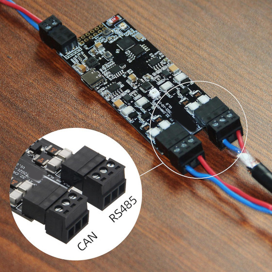
T-CAN485 support
I added T-CAN485 board support, just use the t-can485 branch. It will display states via onboard LED.
Serial control
If you open a serial terminal to the ESP you will see a summary of all variables which reflects CAN messages sent to the Easylink. You can modify these with just typing in.
For example if you want to start the system, type:
ignition on
All CAN frames are now sent.
You can set brightness mode to day or night for example type
brightness night
If you need a new summary of all new states, just hit RETURN without any command.
Available commands:
ignition on/off - power up or shutdown Easylink as normal
ignition standby - let Easylink run in standby mode, for faster recovery after a short stop (it will shutdown after 60 minutes)
brightness night/day - set display brightness and key illumination for day and night usage
mute on/off - disconnect bluetooth and mute system
volume normal/lowered - lower volume and lock volume slider (for reversing)
reverse on/off - toggle rear camera view
gpio on/off - use gpio pins for control (not fully implemented or tested)
CAN frame capture
I captured some CAN frames on CAN Bus on EXT-CAN and replayed then with a arduino and a can transreceiver. I then try to reverse engineer the frames sent to control the Easylink system.
What is working
- Bootup in normal mode
- Standby mode (screen powered off but easylink system stays on for faster recovery on a short stop)
- Set day / night mode
- Set brightness in night mode
- MUTE and bluetooth/disconnect smartphone
- Engage reversing camera
- Lower volume / block volume slider (for reversing)
- Calculate CAN msg for unkown VIN (anti theft)
- Support LiliGo T-CAN485 board
What needs to be done
- Control ESP via GPIOs
- Control ESP via Serial connection
- Reverse engineer of anti-theft / VIN protection calculation
- Test microphone connection
- CAN msg Full MUTE of Easylink
- CAN msg for speed signal (for rising and lowering volume)
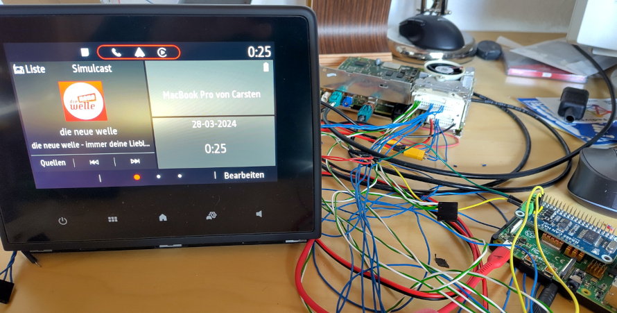
Picture of dumping
Components
-
LilyGo T-CAN485 or
-
ESP32 (using native CAN controller inside) or Arduino-based board with MCP2515
-
VD230 CAN Transreceiver or similar connect to PIN 4 and 5 of ESP32 or NodeMCU32
Connections
Power
Your Easylink system needs power, you can buy a "Car multimedia connector" on aliexpress for example, you need the 20 PIN one. The system gets permanent power connection.
Dont worry it will consumpt less than 1mA during powered off state with no CAN bus activity. If the unit receive some frames power draw goes up to 50mA even the frames are not for the unit itself.
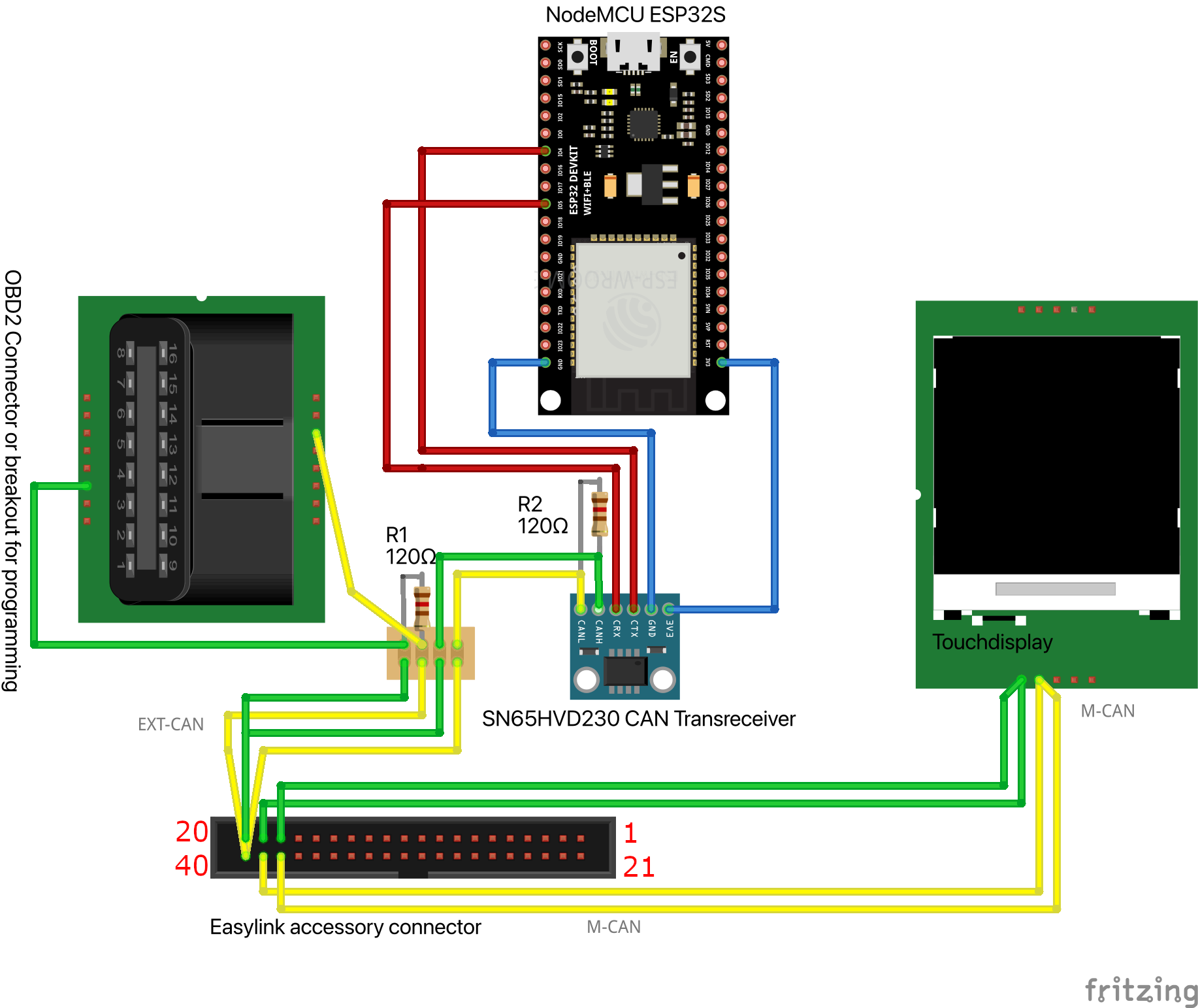
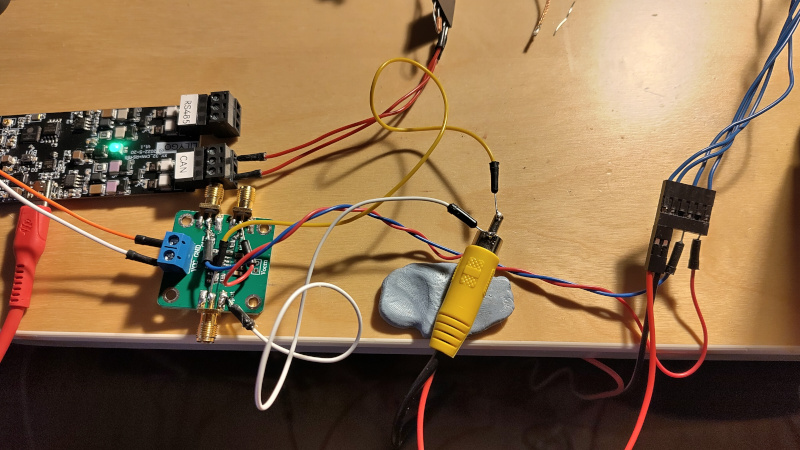
CAN connection
The EXT-CAN which is used to control the Easylink is terminated in CAN gateway which is our ESP32, so you need to terminate your CAN bus at the transreceiver on the ESP side with 120Ohms and on the Easylink side with 120Ohms bedween CAN-low and CAN-high.
Touchdisplay
Likely you will connect a touch display to it, it will use LVDS signaling over a HSD cable. You can buy one off Aliexpress or similar, use the Z Coding (cyan, universal can plug into all color coded sockets) so you dont need mess up with color codes to match the connectors.
The display will be controlled via M-CAN bus which is driven from the Easylink itself. So you need to connect CAN lines from the Easylink to the display and back, because CAN is terminated in the Easylink itself. Of course you can install termination resistors on the display itself.
Picture of CAN wiring
Speaker connections
You want to connect speakers to the system, these connections are located at the power plug. Pinout is below.
Reversing camera connection
If you want to connect a reversing camera, you need a camera which supports differential CVBS signal, standard ones which has only single-ended (one connections is ground, the other is video, most has RCA plugs on it) CVBS output will not work. You can use a single-ended to differential converter like a AD8138 to connect a normal video source to your Easylink.

USB connection
If you want to use USB devices, just grab a USB mini cable and try to plug it into the black USB connector on the easylink, if it fits you can solder a USB-A socket to it and use your devices. If you use a USB hub, use a powered one to not overload USB circuit in the Easylink.
A USB mini to OTG cable will work too, but you must test if the connector fits into the socket or modify it.
Microphone connection
Not tested yet.
Aux Line In connection
Working no problems, not tested AUX pin detection.
Pinouts
Easylink power/speaker connector
| PIN | Description |
|---|---|
| PIN 2 | Front Left + |
| PIN 3 | Front Left - |
| PIN 4 | Rear Left + |
| PIN 5 | Read Left - |
| PIN 11 | Front Right + |
| PIN 12 | Front Right - |
| PIN 13 | Rear Right + |
| PIN 14 | Rear Right - |
| PIN 19 | +12V permanent |
| PIN 20 | Ground |
Beware: Look at the numbers in the Easylink socket, my plug has wrong numbering !
Easylink accessory connector
| PIN | Description |
|---|---|
| PIN 20 | EXT-CAN High (120 Ohms termination required) |
| PIN 40 | EXT-CAN Low (120 Ohms termination required) |
| PIN 19 | M-CAN High (Transreceiver and termination on these pins) |
| PIN 39 | M-CAN Low (Transreceiver and termination on these pins) |
| PIN 18 | M-CAN High (Termination here) |
| PIN 38 | M-CAN Low (Termination here) |
| PIN 1 | Mic 1 Signal |
| PIN 2 | Mic 2 Signal |
| PIN 21 | Mic Common Ground |
| PIN 4 | Aux Detect (you can disable it within DDT) |
| PIN 8 | Aux Ground |
| PIN 7 | Aux Line In Right |
| PIN 27 | Aux Line In Left |
| PIN 12 | Ground for reversing camera |
| PIN 13 | +6V for reversing camera (needs loaded with 300 Ohm to PIN 12, when using 12V camera) |
| PIN 32 | CVBS differential + for reversing camera |
| PIN 33 | CVBS differential - for reversing camera |
Easylink antenna connector
| Color | Description |
|---|---|
| beige | FM Diversity 1 |
| white | FM Diversity 2 |
| brown | DAB (active antenna) |
| blue | GPS (active antenna) |
Active antennas gets phantom power from Easylink
Touch display connector
| PIN | Description |
|---|---|
| PIN 15 | +12V permanent |
| PIN 17 | Ground |
| PIN 11 | M-CAN Low |
| PIN 23 | M-CAN High |
Sourcing hardware
Multimedia connector for power and speakers
https://de.aliexpress.com/item/1005004536283726.html
Automotive connectors for easylink, display
https://de.aliexpress.com/item/1005001933239103.html
40 PIN for the secondary connector on the Easylink itself and 24 PIN for the touch display
https://de.aliexpress.com/item/1005004870099728.html
HSD Cable for Easylink to touch display video connection, use the cyan one which can plug into all sockets
Antenna adapters
https://de.aliexpress.com/item/1005005476955786.html
Fakra to SMA antenna adapters for example, use the cyan ones which can plug into all sockets
Programming with pyren, DDT4all, CLIP or something
You can program the Easylink with mentioned tools like in your car, just make another connection to the EXT-CAN (of course no termination on this point). I have buied a OBD2 socket to breakout cable and connected some dunpont connectors to it, but you can buy a OBD2 Socket and connect it permanent to it for using standard OBD2 dongles.
Setup vehicle configuration
I unplugged my unit from my car and replaced it with a big screen one, so I left my vehicle / CAN bus configuration as is.
If your unit is from another car brand and the unit is not behaving as it should with these CAN messages in my program, set the vehicle configuration to:
- Renault Message Set
- Slot 1 (C1A)
- V-CAN Wakeup C1A
- V-CAN/M-CAN Gateway for ANC/ASC YES
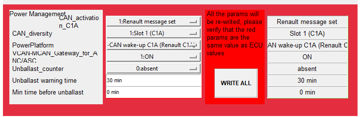
Then it shoud react to commands I reversed engineered. If you have a virgin unit, it will boot up with default settings of course.
Warning about black screen (reboot to death)
During my testing, reversing and so one I programmed a lot with pyren and bricked it from time to time, because not all DDT pages are well coded or I rebooted (key on off reset) too early so changes are not written correctly.
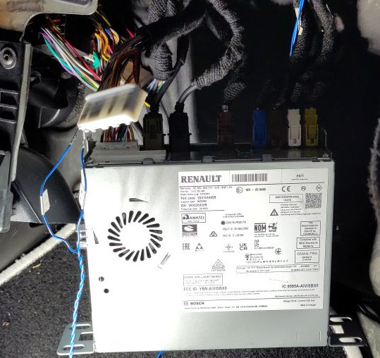
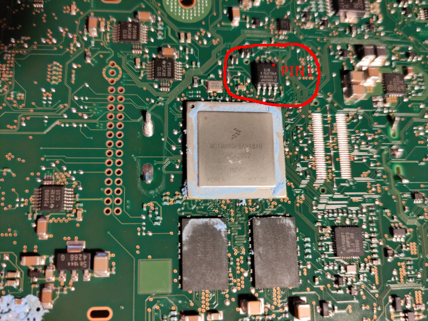
I highly recommend to back up your NOR flash first. It is easy and cheap! Buy a CH341A programmer and a SOIC clip on amazon, ebay or so. Diassembly of the Easylink is easy, remove the few screw from the case and push the top cover off, then remove the two screws holding the pcb on the lower plate.
Then connect the SOIC clip to the 8pin IC near the iMX6 SOC on the PCB back side. The red cable goes to the first pin which is marked with a little dot on the IC.
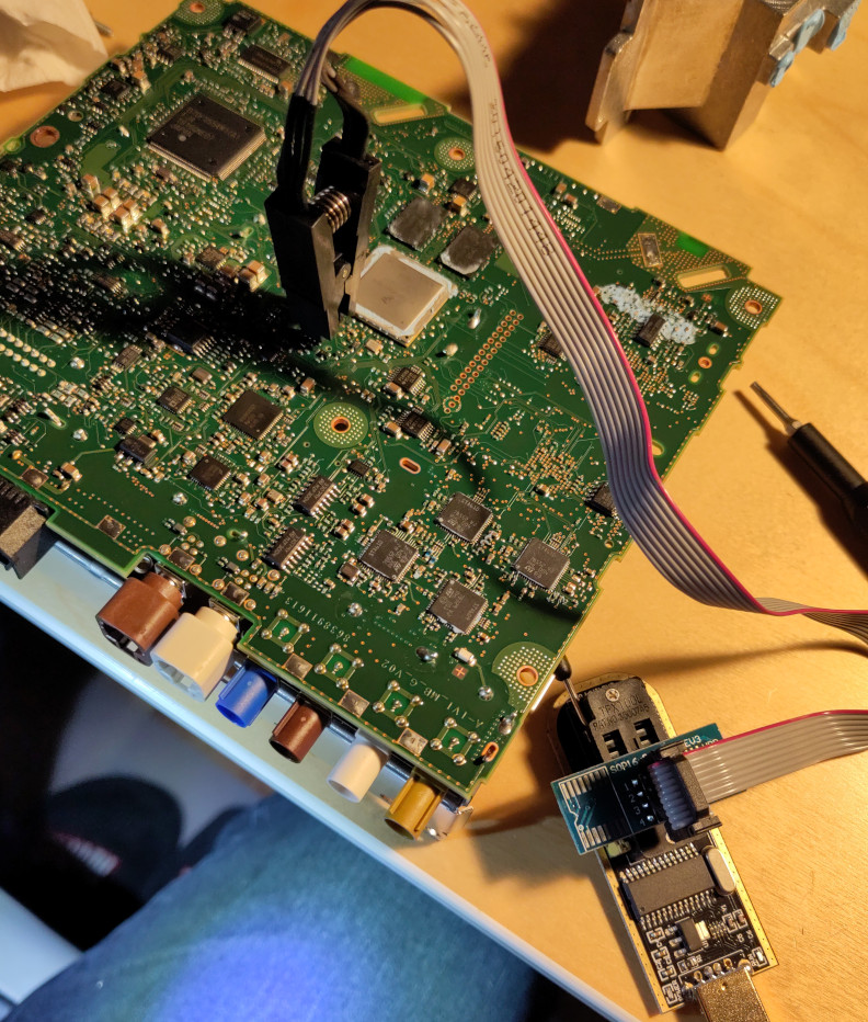
On the programmer software click autodetect IC, and read the contents of it, save it to a file and read it again and save it to another file, then use a compare program (ex. WinMerge) to ensure reading was successfull (both files are exact the same).
If you brick your easylink because of faulty or incompatible configuration and it will not boot any more (screen backlight goes on and off or unit shows press volume to reboot) you can it restore with your backup.
Connect the clip again and erase, write and verify the contents.
Pics of dumping NOR
Anti theft protection (system says locked)
If the unit is from a car which ECUs is partly working (Easylink is starting up in that car it will removed) you can read the CAN message which contains the VIN. You need to connect a CAN sniffer, dongle or something to the V-CAN, M-CAN or EXT-CAN and note the contents of the CAN ID 0x69F.
If you can not capture the 0x69F frame from the donor car, you need to connect via DDT (it will work even it will says locked) and copy the entered VIN. Then calculate the neccessary CAN bytes with the last 7 digits from the VIN number in reverse order and add a F at the last byte. Here is an example:
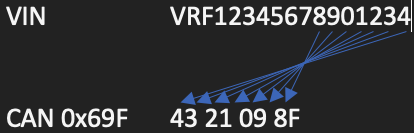
Replace your number in the code and restart the Easylink system.
Debugging
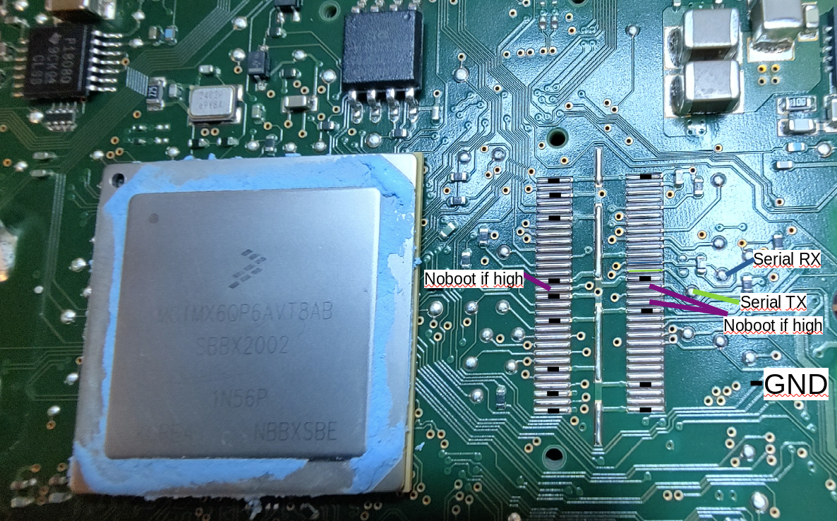
Serial console
Serial console is available at the debug connector near the CPU, with a socket attached it will be possible to access it with case mounted through a latch.
I will be able to stop boot process at uboot prompt but I cannot enter any commands. If the unit is booting in normal Linux with eMMC fastboot, you will not be able to see uboot console. In normal Linux system there are no login or any shell accessible.
root access
Is not easy possible at the moment. There is a SSH server active without password, but firewall protects it. It is neccessary to modify content of the eMMC. You can modify firewall rules to access ssh via WiFi or spawn a console on serial console port with adding a tty via systemd on /dev/ttymcx3.
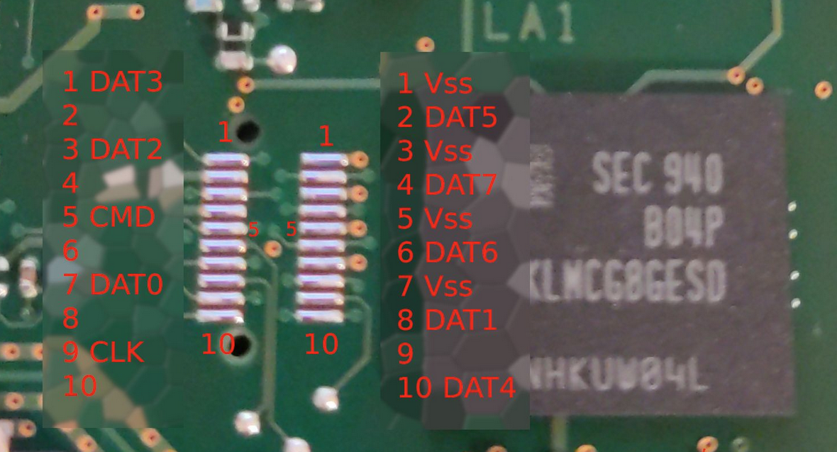
eMMC pinout
I dumped the whole eMMC from a locked ebay unit with desoldering it. I wrote down all PINs to the eMMC, so we can try to connect it without desoldering and risk to damage the PCB.
Help me
If you want to help you can spent me a coffee (Paypal: casc@pfalz-mail.de) or you can contribute yourself to this project.
Feel free to optimize the code, reverse some CAN messages, reverse the VIN calculation, raise an issue or ask questions.
Contributions
thomsoon Anti theft CAN frame calculation