| .. | ||
| main | ||
| CMakeLists.txt | ||
| eth2ap.png | ||
| Makefile | ||
| README.md | ||
| sdkconfig.defaults | ||
eth2ap Example
(See the README.md file in the upper level 'examples' directory for more information about examples. To try a more complex application about Ethernet to WiFi data forwarding, please go to iot-solution.)
Note: This example uses some internal APIs (e.g. esp_wifi_internal_tx) which might get changed between minor versions of ESP-IDF.
Overview
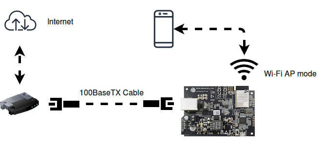
The similarities on MAC layer between Ethernet and Wi-Fi make it easy to forward packets from Ethernet to Wi-Fi and vice versa. This example illustrates how to implement a simple "router" which only supports forwarding packets between Ethernet port and Wi-Fi AP interface. In this case, the Ethernet should play the role of WAN (i.e. it can access outside network) so that a mobile device could get access to the Internet when it gets connected to ESP32 through Wi-Fi.
Note: In this example, ESP32 works like a bridge between Ethernet and Wi-Fi, and it won't perform any actions on Layer3 and higher layer, which means there's no need to initialize the TCP/IP stack.
How to use example
Hardware Required
To run this example, it's recommended that you have an official ESP32 Ethernet development board - ESP32-Ethernet-Kit. This example should also work for 3rd party ESP32 board as long as it's integrated with a supported Ethernet PHY chip. Up until now, ESP-IDF supports up to four Ethernet PHY: LAN8720, IP101, DP83848 and RTL8201, additional PHY drivers should be implemented by users themselves.
Besides that, esp_eth component can drive third-party Ethernet module which integrates MAC and PHY and provides common communication interface (e.g. SPI, USB, etc). This example will take the DM9051 as an example, illustrating how to install the Ethernet driver in the same manner.
Pin Assignment
See common pin assignments for Ethernet examples from upper level.
Configure the project
idf.py menuconfig
In addition to the common configurations for Ethernet examples from upper level, you might also need to update the default value of following configurations:
In the Example Configuration menu:
- Set the SSID and password for Wi-Fi ap interface under
Wi-Fi SSIDandWi-Fi Password. - Set the maximum connection number under
Maximum STA connections.
Build, Flash, and Run
Build the project and flash it to the board, then run monitor tool to view serial output:
idf.py -p PORT build flash monitor
(Replace PORT with the name of the serial port to use.)
(To exit the serial monitor, type Ctrl-].)
See the Getting Started Guide for full steps to configure and use ESP-IDF to build projects.
Example Output
Step 1: Initialize Ethernet and Wi-Fi (AP mode)
I (508) example: Power On Ethernet PHY
I (518) system_api: Base MAC address is not set, read default base MAC address from BLK0 of EFUSE
I (518) emac: emac reset done
I (518) example: Ethernet Started
......
I (538) wifi: wifi driver task: 3ffc7fbc, prio:23, stack:3584, core=0
I (538) system_api: Base MAC address is not set, read default base MAC address from BLK0 of EFUSE
I (538) system_api: Base MAC address is not set, read default base MAC address from BLK0 of EFUSE
I (568) wifi: wifi firmware version: ec61a20
I (568) wifi: config NVS flash: enabled
I (568) wifi: config nano formating: disabled
I (568) wifi: Init dynamic tx buffer num: 32
I (568) wifi: Init data frame dynamic rx buffer num: 32
I (578) wifi: Init management frame dynamic rx buffer num: 32
I (588) wifi: Init management short buffer num: 32
I (588) wifi: Init static rx buffer size: 1600
I (588) wifi: Init static rx buffer num: 10
I (598) wifi: Init dynamic rx buffer num: 32
Step 2: Ethernet Connects to Router/Switch/PC (with DHCP server enabled)
I (4518) example: Ethernet Link Up
Step 3: Start Wi-Fi AP
I (4618) phy: phy_version: 4100, 2a5dd04, Jan 23 2019, 21:00:07, 0, 0
I (4618) wifi: mode : softAP (30:ae:a4:c6:87:5b)
I (4628) wifi: Total power save buffer number: 16
I (4628) wifi: Init max length of beacon: 752/752
I (4628) wifi: Init max length of beacon: 752/752
Step 4: Wi-Fi station (e.g. mobile phone) connects to ESP32's Wi-Fi
I (10168) wifi: new:<1,0>, old:<1,0>, ap:<1,1>, sta:<255,255>, prof:1
I (10168) wifi: station: c4:0b:cb:ec:9a:84 join, AID=1, bgn, 20
I (10258) example: AP got a station connected
Now your mobile phone should get access to the Internet.
Troubleshooting
See common troubleshooting for Ethernet examples from upper level.
- If you got error message like
WiFi send packet failedwhen running the example, you may need to enlarge the value ofFLOW_CONTROL_WIFI_SEND_DELAY_MSin "ethernet_example_main.c", because Ethernet process packets faster than Wi-Fi on ESP32. - If you got error message like
send flow control message failed or timeoutwhen running the example, you may need to enlarge the value ofFLOW_CONTROL_QUEUE_LENGTHin "ethernet_example_main". - Wi-Fi station doesn't receive any IP via DHCP?
- All Layer 3 (TCP/IP functions) on the ESP32 are disabled, including the SoftAP DHCP server. This means that devices must be able to access another DHCP server (for example on a Wi-Fi router connected via ethernet) or should use statically assigned IP addresses.
(For any technical queries, please open an issue on GitHub. We will get back to you as soon as possible.)