* Use "example" in all example function & variable names, ie use i2c_example_xxx instead of i2c_xxx for example functions. Closes #198 https://github.com/espressif/esp-idf/issues/198 * Mark example functions, etc. static * Replace uses of "test" & "demo" with "example" * Split the UART example into two * Rename "main" example files to end with "_main.c" for disambiguation |
||
|---|---|---|
| .. | ||
| main | ||
| Makefile | ||
| OTA_workflow.png | ||
| README.md | ||
| sdkconfig.defaults | ||
Simple OTA Demo
This example demonstrates a working OTA (over the air) firmware update workflow.
This example is a simplified demonstration, for production firmware updates you should use a secure protocol such as HTTPS.
Aim
An app running on ESP32 can upgrade itself by downloading a new app "image" binary file, and storing it in flash.
In this example, the ESP32 has 3 images in flash: factory, OTA_0, OTA_1. Each of these is a self-contained partition. The number of OTA image partition is determined by the partition table layout.
Flashing the example over serial with "make flash" updates the factory app image. On first boot, the bootloader loads this factory app image which then performs an OTA update (triggered in the example code). The update downloads a new image from an http server and saves it into the OTA_0 partition. At this point the example code updates the ota_data partition to indicate the new app partition, and resets. The bootloader reads ota_data, determines the new OTA image has been selected, and runs it.
Worflow
The OTA_workflow.png diagram demonstrates the overall workflow:
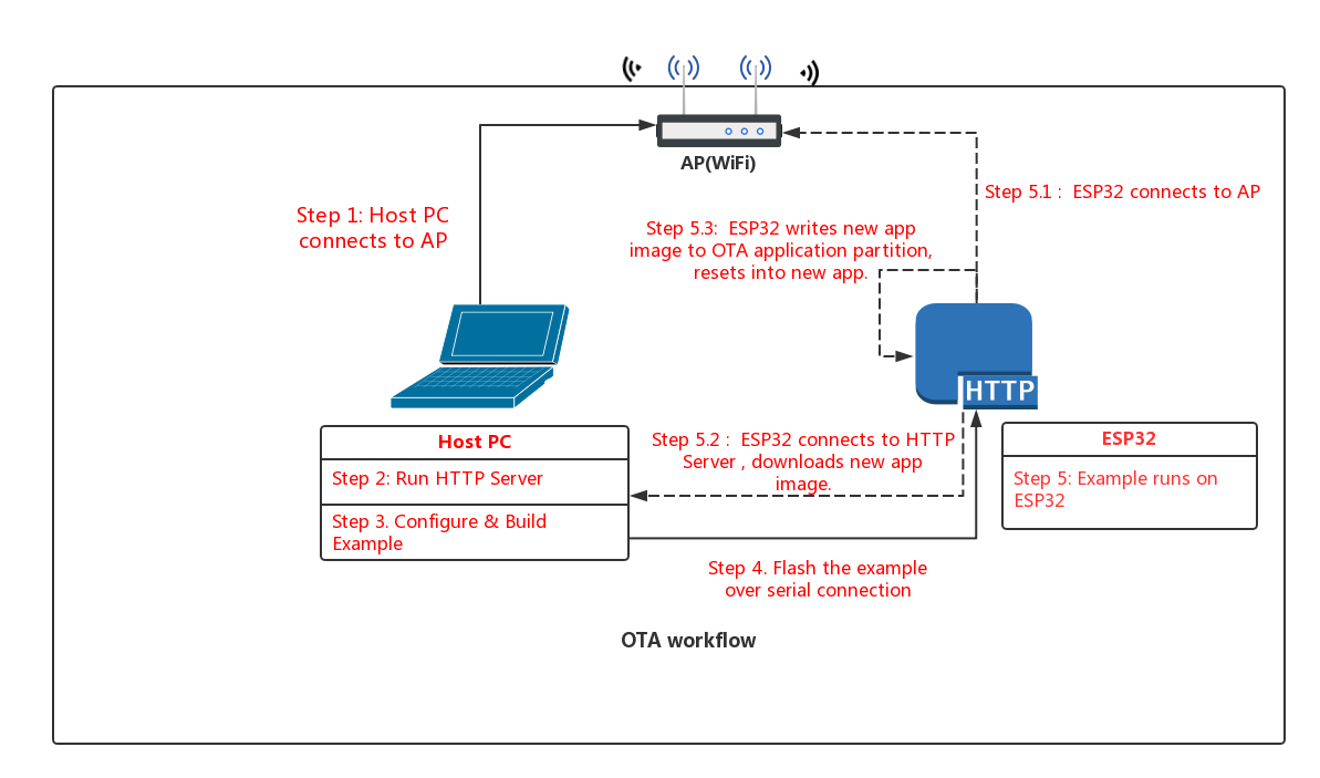
Step 1: Connect to AP
Connect your host PC to the same AP that you will use for the ESP32.
Step 2: Run HTTP Server
Python has a built-in HTTP server that can be used for example purposes.
For our upgrade example OTA file, we're going to use the get-started/hello_world example.
Open a new terminal to run the HTTP server, then run these commands to build the example and start the server:
cd $IDF_PATH/examples/get-started/hello_world
make
cd build
python -m SimpleHTTPServer 8070
While the server is running, the contents of the build directory can be browsed at http://localhost:8070/
NB: On some systems, the command may be python2 -m SimpleHTTPServer.
NB: You've probably noticed there is nothing special about the "hello world" example when used for OTA updates. This is because any .bin app file which is built by esp-idf can be used as an app image for OTA. The only difference is whether it is written to a factory partition or an OTA partition.
If you have any firewall software running that will block incoming access to port 8070, configure it to allow access while running the example.
Step 3: Build OTA Example
Change back to the OTA example directory, and type make menuconfig to configure the OTA example. Under the "Example Configuration" submenu, fill in the following details:
- WiFi SSID & Password
- IP address of your host PC as "HTTP Server"
- HTTP Port number (if using the Python HTTP server above, the default is correct)
If serving the "hello world" example, you can leave the default filename as-is.
Save your changes, and type make to build the example.
Step 4: Flash OTA Example
When flashing, use the erase_flash target first to erase the entire flash (this deletes any leftover data in the ota_data partition). Then flash the factory image over serial:
make erase_flash flash
(The make erase_flash flash means "erase everything, then flash". make flash only erases the parts of flash which are being rewritten.)
Step 5: Run the OTA Example
When the example starts up, it will print "ota: Starting OTA example..." then:
- Connect to the AP with configured SSID and password.
- Connect to the HTTP server and download the new image.
- Write the image to flash, and configure the next boot from this image.
- Reboot
Troubleshooting
- Check your PC can ping the ESP32 at its IP, and that the IP, AP and other configuration settings are correct in menuconfig.
- Check if any firewall software is preventing incoming connections on the PC.
- Check you can see the configured file (default hello-world.bin) if you browse the file listing at http://127.0.0.1/
- If you have another PC or a phone, try viewing the file listing from the separate host.
Error "ota_begin error err=0x104"
If you see this error then check that the configured (and actual) flash size is large enough for the partitions in the partition table. The default "two OTA slots" partition table only works with 4MB flash size. To use OTA with smaller flash sizes, create a custom partition table CSV (look in components/partition_table) and configure it in menuconfig.
If changing partition layout, it is usually wise to run "make erase_flash" between steps.
Production Implementation
If scaling this example for production use, please consider:
- Using an encrypted communications channel such as HTTPS.
- Dealing with timeouts or WiFi disconnections while flashing.