| .. | ||
| main | ||
| CMakeLists.txt | ||
| eth2ap.png | ||
| Makefile | ||
| README.md | ||
| sdkconfig.defaults | ||
eth2ap Example
(See the README.md file in the upper level 'examples' directory for more information about examples. To try a more complex application about Ethernet to WiFi data forwarding, please go to iot-solution.)
Overview
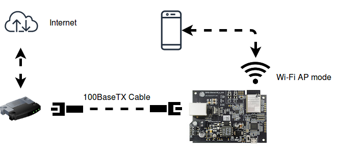
The similarities on MAC layer between Ethernet and Wi-Fi make it easy to forward packets from Ethernet to Wi-Fi and vice versa. This example illustrates how to implement a simple "router" which only supports forwarding packets between Ethernet port and Wi-Fi AP interface. In this case, the Ethernet should play the role of WAN (i.e. it can access outside network) so that a mobile device could get access to the Internet when it gets connected to ESP32 through Wi-Fi.
Note: In this example, ESP32 works like a bridge between Ethernet and Wi-Fi, and it won't perform any actions on Layer3 and higher layer, which means there's no need to initialize the TCP/IP stack.
How to use this example
Hardware Required
To run this example, it's recommended that you have an official ESP32 Ethernet development board - ESP32-Ethernet-Kit. This example should also work for 3rd party ESP32 board as long as it's integrated with a supported Ethernet PHY chip. Up until now, ESP-IDF supports three Ethernet PHY: TLK110, LAN8720 and IP101, additional PHY drivers should be implemented by users themselves.
Configure the project
Enter make menuconfig if you are using GNU Make based build system or enter idf.py menuconfig if you are using CMake based build system. Then go into Example Configuration menu.
-
Choose PHY device under
Ethernet PHY Device, by default, the ESP32-Ethernet-Kit has anIP101on board. -
Set PHY address under
Ethernet PHY address, it should depend on the PHY configuration of your hardware. You'd better consult the schematic of the board. By default, the PHY address of ESP32-Ethernet-Kit is 1. -
Check whether or not to control the power of PHY chip under
Use PHY Power (enable / disable) pin, (if set true, you also need to give the GPIO number of that pin underPHY Power GPIO). -
Set SMI MDC/MDIO GPIO number according to board schematic, by default they are set as below:
Default Example GPIO RMII Signal Notes GPIO23 MDC Output to PHY GPIO18 MDIO Bidirectional -
Select one kind of RMII clock mode under
Ethernet RMII Clock Modeoption. Possible configurations of the clock are listed as below. By default, ESP32-Ethernet-Kit use theGPIO0 inputmode, which gives a good performance when enabling Ethernet and Wi-Fi at the same time.Mode GPIO Pin Signal name Notes external GPIO0 EMAC_TX_CLK Input of 50MHz PHY clock internal GPIO0 CLK_OUT1 Output of 50MHz APLL clock internal GPIO16 EMAC_CLK_OUT Output of 50MHz APLL clock internal GPIO17 EMAC_CLK_180 Inverted output of 50MHz APLL clock (suitable for long clock trace) - External RMII clock must be connected to
GPIO0. - ESP32 can generate the RMII clock(50MHz) using its internal APLL. But if the APLL has already been used for other peripheral (e.g. I²S), you'd better choose the external clock.
- External RMII clock must be connected to
-
Set the SSID and password for Wi-Fi ap interface under
Wi-Fi SSIDandWi-Fi Password. -
Set the maximum connection number under
Maximum STA connections.
Build and Flash
To build and flash the example, enter make -j4 flash monitor if you are using GNU Make based build system or enter idf.py build flash monitor if you are using CMake based build system.
(To exit the serial monitor, type Ctrl-].)
See the Getting Started Guide for full steps to configure and use ESP-IDF to build projects.
Example Output
Step 1: Initialize Ethernet and Wi-Fi (AP mode)
I (508) example: Power On Ethernet PHY
I (518) system_api: Base MAC address is not set, read default base MAC address from BLK0 of EFUSE
I (518) emac: emac reset done
I (518) example: Ethernet Started
......
I (538) wifi: wifi driver task: 3ffc7fbc, prio:23, stack:3584, core=0
I (538) system_api: Base MAC address is not set, read default base MAC address from BLK0 of EFUSE
I (538) system_api: Base MAC address is not set, read default base MAC address from BLK0 of EFUSE
I (568) wifi: wifi firmware version: ec61a20
I (568) wifi: config NVS flash: enabled
I (568) wifi: config nano formating: disabled
I (568) wifi: Init dynamic tx buffer num: 32
I (568) wifi: Init data frame dynamic rx buffer num: 32
I (578) wifi: Init management frame dynamic rx buffer num: 32
I (588) wifi: Init management short buffer num: 32
I (588) wifi: Init static rx buffer size: 1600
I (588) wifi: Init static rx buffer num: 10
I (598) wifi: Init dynamic rx buffer num: 32
Step 2: Ethernet Connects to Router/Switch/PC (with DHCP server enabled)
I (4518) example: Ethernet Link Up
Step 3: Start Wi-Fi AP
I (4618) phy: phy_version: 4100, 2a5dd04, Jan 23 2019, 21:00:07, 0, 0
I (4618) wifi: mode : softAP (30:ae:a4:c6:87:5b)
I (4628) wifi: Total power save buffer number: 16
I (4628) wifi: Init max length of beacon: 752/752
I (4628) wifi: Init max length of beacon: 752/752
Step 4: Wi-Fi station (e.g. mobile phone) connects to ESP32's Wi-Fi
I (10168) wifi: new:<1,0>, old:<1,0>, ap:<1,1>, sta:<255,255>, prof:1
I (10168) wifi: station: c4:0b:cb:ec:9a:84 join, AID=1, bgn, 20
I (10258) example: AP got a station connected
Now your mobile phone should get access to the Internet.
Troubleshooting
-
Got error message
emac: emac rx buf errwhen running the example.- This example just forwards the packets on the Layer2 between Wi-Fi and Ethernet, it won't do any Layer3 business. So make sure you have disabled the
CONFIG_ETH_EMAC_L2_TO_L3_RX_BUF_MODE. By default, this option is false in thesdkconfig.defaultsfile.
- This example just forwards the packets on the Layer2 between Wi-Fi and Ethernet, it won't do any Layer3 business. So make sure you have disabled the
-
Got error message
example: WiFi send packet failed: -1when running the example.- Ethernet process packets faster than Wi-Fi on ESP32, so have a try to enlarge the value of
FLOW_CONTROL_WIFI_SEND_DELAY_MS.
- Ethernet process packets faster than Wi-Fi on ESP32, so have a try to enlarge the value of
-
Wi-Fi station doesn't receive any IP via DHCP.
- All Layer 3 (TCP/IP functions) on the ESP32 are disabled, including the SoftAP DHCP server. This means that devices must be able to access another DHCP server (for example on a Wi-Fi router connected via ethernet) or should use statically assigned IP addresses.